
How Is Wire Gauge Measured?
How Is Wire Gauge Measured?
In manufacturing, small details often determine whether your build works flawlessly or fails completely.
Wire gauge is one of those details. It determines how safely and efficiently current moves through your product.
If a wire is undersized, it overheats. If it’s oversized, it drives up costs and takes up unnecessary space. Either way, you have a problem. Luckily, it can be solved by understanding how wire gauge is measured.
Wire gauge is a standardized method for describing the size of the metal conductor inside a wire. The thicker the conductor, the more current it can handle and the less resistance it creates.
But wire sizing can be confusing. Different systems, materials, and standards define size in different ways. In the sections below, we’ll break it down simply and show how manufacturers maintain consistency.
How Wire Gauge Is Measured
Wire gauge is based on the size of the conductor itself, not the total diameter of the insulated wire.
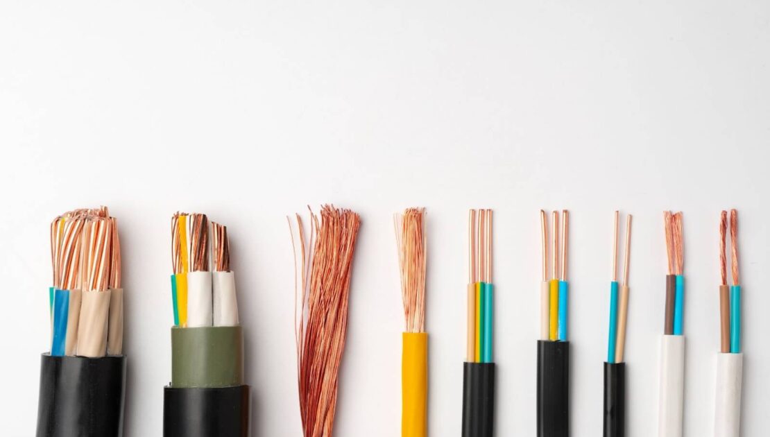
For solid wire, the measurement is simple: manufacturers measure the bare metal diameter with calipers or a micrometer.
For stranded wire, the gauge reflects the total metal area of all strands combined, not the overall bundle thickness, which includes small air gaps between strands.
Most wire is printed with its gauge and type so technicians can verify size and compliance before assembly. In production environments, wire gauge plates, calipers, or automated inspection tools confirm that the material supplied matches the specified size and standards.
Several different systems are used around the world to describe these measurements.
American Wire Gauge (AWG)
AWG is the most common system in North America, where a number is assigned to each wire size. The lower the number, the thicker the conductor and the more current it can carry. AWG is used widely in electronic assemblies, harnesses, and PCB wiring.
Metric (mm²)
The metric system is used throughout much of the world, expressing wire size as the conductor’s cross-sectional area (for example, 0.5 mm² or 1.0 mm²). Metric sizes appear frequently in automotive, industrial, and export builds.
Other Systems
Two other standards appear occasionally. Standard Wire Gauge (SWG) is an older British system that predates AWG, while kcmil or MCM identifies large power conductors used in heavy equipment or infrastructure.
Regardless of the system, the goal remains the same: to establish a consistent and traceable method for sizing wire, ensuring that every connection performs safely and predictably.
How Conductor Material Affects Wire Gauge
Different conductor materials change how wire gauge corresponds to current capacity and long-term reliability.
Copper
Copper is the baseline for most electronic assemblies and the reference point for gauge charts. Because of its high conductivity, copper wire can carry more current through a smaller diameter than most other materials.
Tinned Copper
Tinned copper has the same electrical properties as bare copper but includes a thin tin coating to resist corrosion and simplify soldering. It doesn’t change the gauge itself, but it improves reliability and ease of assembly over time.
Aluminum
Aluminum conducts electricity less effectively than copper, so it needs a thicker cross-section to carry the same current. In practice, this means an aluminum wire labeled with the same gauge as a copper wire will handle less current.
Your choice of materials will define how gauge values translate into real-world performance. It’s an important factor in ensuring consistent conductivity, strength, and long-term reliability.
Choosing the Right Wire Gauge
Selecting the right wire gauge starts with understanding what the wire needs to do. The goal is to balance electrical performance, mechanical fit, and manufacturability.
Current and Voltage Requirements
Thicker wire carries more current with less voltage loss, while thinner wire suits low-power or signal applications. Matching gauge to load ensures stable performance and prevents overheating.
Run Length and Routing
Longer runs increase resistance, which can cause voltage drop. Choosing a slightly larger gauge helps maintain consistent power across distance.
Application Type
Signal lines often use finer wire, such as 24 AWG, for flexibility and compact routing. Power lines or high-current paths may require 16 AWG or larger to handle the load safely.
Manufacturing Considerations
Wire must also fit properly within terminals, crimps, and connectors. Using consistent gauge sizes across assemblies simplifies tooling, reduces setup time, and supports repeatable quality.
In practice, engineers refer to design guidelines and ampacity charts during the development phase. Once a product moves to production, verifying the correct gauge at each step keeps builds efficient, compliant, and consistent.
Common Mistakes When Selecting Wire Gauge
Even small errors in wire sizing can lead to costly issues later in production or testing. These are some of the most frequent mistakes manufacturers encounter.
Selecting Wire by Outer Diameter
It’s easy to mistake the total thickness of a wire for its gauge, but insulation adds bulk without affecting how much current the wire can carry. Gauge refers only to the size of the metal conductor inside, not the full cable diameter.
Mixing Measurement Systems
AWG and metric sizes don’t match up directly. Swapping one for the other without converting can result in loose fits, unreliable crimps, or electrical performance that doesn’t meet design requirements.
Ignoring Connector and Crimp Compatibility
Every terminal and crimp tool is designed for a specific wire range. Using a wire that’s even slightly outside that range can cause weak mechanical retention or failed pull tests. These issues are easy to miss until inspection or field use.
Overcompensating with Larger Wire
Choosing thicker wire might seem safer, but it often creates new problems. Heavier wire adds stiffness, takes up space, and can complicate routing in compact assemblies without providing any real performance advantage.
Skipping Verification Checks
Assuming a wire meets spec without confirming it is a common and costly oversight. Checking gauge markings, validating tooling settings, and performing quick inspections all help ensure consistency across builds.
Each of these mistakes is avoidable with careful design reviews, proper documentation, and routine verification on the production floor.
Why Wire Gauge Matters
Wire gauge may seem like a small specification, but it influences nearly every aspect of a product’s performance, safety, and manufacturability.
Electrical Performance
The size of the conductor determines how much current it can carry and the amount of resistance it adds to a circuit. Undersized wire struggles to carry current efficiently, leading to heat and power loss. Oversized wire introduces bulk and cost that offer no real benefit.
Mechanical Fit
Each gauge corresponds to specific terminals, crimps, and connector housings. The wrong combination can cause poor contact, loose connections, or premature failures during testing.
Manufacturing Efficiency
Consistent gauge selection streamlines setup, tooling, and quality checks, especially in high-mix production environments where dozens of wire types may be used in a single build.
Compliance and Safety
Standards like UL, CSA, and IPC/WHMA-A-620 require the correct conductor size for every connection. Following these standards ensures every assembly meets both electrical and mechanical safety requirements.
Wire gauge connects design intent with reliability on the production floor. Choosing the right size keeps assemblies efficient, durable, and compliant.
How August Electronics Ensures Accuracy
At August Electronics, every wire used in production is verified for gauge, material, and certification before assembly begins. Incoming inspection confirms that each spool meets UL or CSA standards and matches the specifications outlined in the build documentation.
During production, technicians use calibrated tooling and controlled crimp heights to maintain reliable terminations. Automated checks and in-process inspections confirm that every conductor is the correct size and properly installed.
Each assembly is built to IPC/WHMA-A-620 workmanship standards, ensuring consistent quality across every connection. By maintaining tight control over wire gauge and material selection, we help clients achieve safe, compliant, and repeatable builds from their first prototype to full-scale production.
Partner with us to make sure every detail of your build is correct from the start.